

Introduction: A Shop Floor Scene, A Surprising Number, And One Big Question
Picture this: a humid afternoon on a Caribbean dock, forklifts moving quick, and a solar microgrid humming steady. The work never stops, and backup power better not blink. The lifepo4 lithium battery keeps that rhythm clean and calm, day in, day out. Now add the data: global demand for LiFePO4 packs is rising fast, with factories racing to scale capacity while cutting defects by double digits. But here’s the rub—can the way we kick off a cell’s life in the factory actually make or break the long-term performance (and the peace of mind) we expect?
Mi a tell yuh, the start matters. The early charge‑discharge steps set the tone for cycle life, safety headroom, and how well the BMS reads the truth. So, what’s really happening on those formation lines, and why do little drifts become big headaches later? Let’s bridge the gap from shipping yard to smart line control, quick-quick. On to the deeper layer.
Under the Hood: Formation’s Hidden Pain Points in Plain Sight
Why do lines still bottleneck?
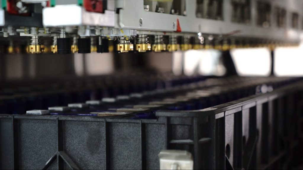
In formation manufacturing, cells get their first controlled charge and discharge to establish SEI quality and stabilize capacity. Sounds routine. But the friction lives in the details: mixed racks of cells with slight impedance spread, power converters that respond in milliseconds (not microseconds), and calibration drift across channels that the MES can’t always catch in real time. As we saw in the opening, demand keeps climbing, yet operators still fight queuing delays, uneven heat zones, and SOC estimation noise that later confuses BMS algorithms—funny how that works, right?
Look, it’s simpler than you think: small variances in current ripple or thermal gradients during early cycles can hardwire uneven performance. That shows up months later as weak peak power or a pack that trips protection early. Edge computing nodes can help, but many lines still run batch reports, not live controls. The result? Pain points that hide in plain sight—channel-to-channel mismatch, incomplete cell matching rules, and limited traceability linking each micro-step to final pack behavior. Traditional fixes focus on throughput alone; the better fix aligns process windows to the cell’s electrochemistry while feeding live data to the MES and the future BMS firmware. That’s the pivot.
Comparative Insight: New Principles Steering the Next Wave
What’s Next
So where do we go from here? The shift is toward closed-loop control that treats formation manufacturing as a dynamic system, not a fixed recipe. New technology principles are emerging: fast current control with sub-millisecond response, synchronized temperature sensing per slot, and adaptive profiles that change steps based on live impedance trends. Instead of one-size-fits-all CC-CV, lines use micro-adjustments guided by a simple model of SEI growth and lithium plating risk. Data from early cycles trains the SOC model that the BMS will rely on later—so the pack ships with fewer surprises. And when variance spikes, the line flags and reroutes cells to a tailored path, not a generic queue.
Compared with “run it and log it,” this approach treats data as a control input—not just a record. It reduces rework, narrows capacity spread, and brings channel calibration into the same loop as quality checks. The same logic stretches to pack assembly: better cell grouping, tighter thermal maps, cleaner diagnostics. The payoff isn’t only yield; it’s predictability under real loads and in edge cases—storms, fast charge, high C-rate bursts. And yes, the dock worker doesn’t care about impedance spectroscopy. They want the lights steady. That’s the mission, full stop—funny how mission clarity makes tech choices easier, right?

Before we wrap, three clear metrics to judge any next-gen formation line or solution—use them, and you’ll pick winners more often than not. One: error band for channel calibration under load (target sub-0.1% current, sub-1 mV voltage drift). Two: thermal uniformity per rack during peak steps (delta under 1.5°C helps prevent plating). Three: traceable linkage from formation features to downstream pack KPIs (cycle fade at 0.5C/25°C, retention at high temp) with pass/fail tied back to process windows. If a provider can show those, plus live control tied to formation manufacturing data, you’re in good shape. For deeper domain context without the hype, see LEAD.